| Stockcode | : | 663785 |
| Type | : | Saws |
| Subtype | : | Miscellaneous |
| Manufacturer | : | HEM |
| Model | : | PHM 20/144 |
| Year | : | 1997 |
| Price | : | P.O.A. |
| Description | : | |
|
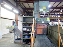
Used Hem Vertical Plate Saw
Model: PHM 20/144 ♦ YEAR: 1997 Stock No: 8256 The Hem Vertical Plate Saw provides the needed mechanisms for positioning, feeding and sawing plate at an economical cost. It is a versatile and rugged machine. This machine will allow cutting in parallel to the table. You can position the head for various widths without repositioning the material. You can also cut perpendicular to the table by using right angle guides, which are provided with the machine. Specifications: Blade to column: 20” Maximum work height: 20” Maximum cut length: 144” Blade size: 1-1/2” x 19’10” Blade Speed: 70-360 sfpm infinitely variable Table capacity: 12,000 lbs Motor: 15 HP, 220/440 volt, 3 phase (currently wired 440 volt) AC-speed controlled by a variable frequency controller Carriage table: Electrically driven by a Vector drive Hydraulics: 2 HP, 220/440 volt Equipped with: Chip Conveyor: Chip Conveyor System to convey chips from the sawing area to a remote chip box for easier removal Cut Watcher System: A system that monitors the cut for squareness to a pre-set deviation value. The system shuts down the saw when the pre-set value is exceeded. Controls: Control console mounted at normal operation station to control hydraulic and electrical functions and includes: emergency stop, power, forward-reverse (with feed ranges for feeding material), and power. Computer Keypad Functions: The Hem Saw Table Feed Rate Computer is designed to provide the saw operation maximum control of the workpiece being cut. This is accomplished by allowing the material to be traversed in either of the two selectable modes: A) Constant Linear Speed Mode: In this mode the feed table is moved forward at a constant speed. This speed is determined by the operator and input to the computer in the form of “inch per minute”. B) Square Inches per Minute Mode: In this mode the traverse rate is calculated by the computer based on the desired cutting rate and the material size input to the computer. Both modes provide a high degree of precise control over the cutting operation while displaying current feed rates and time in cut to the operator Description of keypad function: Number keys (0-9): Used to enter desired feed rates and material heights to the computer Arrow keys (up-down): Used to increase or decrease feed rates and display alternate data Set height: Instructs the computer that the material size is to be entered Set rate: Instructs the computer that the desired feed rate is to be entered. Set start position: Tells the computer the zero point for the depth to cut Enter key: Instructs the computer to actuate the users command Enter depth of cut: Instructs the computer how deep the cut should be. When the desired depth is reached, the cut will cease and the blade motor will stop Clear key: Instructs the computer to cancel its current operation. Clears the display and resets to zero. Stop key: Instructs the computer to stop all motion, but will not clear the display or rest any entered data. Stop key: Instructs the computer to stop all motion, but will not clear the display or reset any entered data. Time key: Instructs the computer to display the current time in cut while the time key is depressed Start cut button: Pressing the start cut button instructs the table to commence moving and the cut starts Break in: Run break in mode. Slower cutting rate than to assigned rate at set time. The cutting rate valve is at 50% of the assigned cutting rate and increases 10% every 5 minutes until the assigned cutting rate is reached. The 5 minute interval can be adjusted by the operator Exit mode: Exit rate is decreased to reduce the possibility of the blade locking up in the cut. Also prevents chipping of the teeth. Reduction is approximately 50%. This can be adjusted by the operator. Sequence of operation: 1. Carriage table assembly is sent to the load position: A) Head will be positioned manually by the use of power switches for the depth of cut 2. The material is placed on carriage table assembly 3. Material is secured to the carriage table assembly 4. Set guide arm height 5. Turn the motor on and set the blade speed 6. Select the carriage assembly “forward” position and set the desired feed range 7. While the machine is cutting you may adjust the feed (cutting rate) 8. When the machine has complete the cut, turn the motor off 9. Remove and reposition material as necessary Saw arm assembly: ♦ Heavy duty construction with 28” (711mm) band wheels ♦Powered blade tension to assure proper and constant band tension ♦All flat, carbide guides for rigid and accurate blade support ♦Powered positioning of guide arm to a maximum height of 25” ♦Blade drive system consists of a 15 HP motor for maximum blade use through a totally enclosed, running in oil, worm gear drive for smooth operation ♦Blade speed change in front of saw for easy access (70-360 SFPM) ♦Operator can push a button to manually move the head in or out or enter into the computer an specific distance ♦This feature will let you cut slabs off of a billet or plate without repositioning or reclamping the material. The benefits of this feature is that the cuts will be parallel because the material is not moved Carriage table assembly: ♦Consists of two (2) each heavy duty 4-3/4” steel plates weighing approximately 5,000 lbs each ♦Consists of 25” wide rollers, 4” in diameter, placed on 4-1/2” centers ♦Carriage table supports plate weighing up to 15,000 lbs ♦Table has 2-1/4” deep slots and 5” wide channels to clear loading chains or straps ♦To locate the material on the moving table, the side of the table is machined and on a parallel plane with the saw cut to .030 over 144” Standard Equipment • Powered blade brush • Chip removal system • Cut watcher system • Powered guide arm • Depth stop to limit stroke of table • Computer controlled cutting • Work light • Right angle guides: This feature will allow cutting perpendicular to the travel of the table – 25” capacity. This feature will allow a perpendicular cut to the standard cut on the same part. The standard cut must be made and the arm must be backed out, then the right angle guides are installed for the second cut. Head traversing speed is determined by the computer exactly as the table traverse speed. | ||
| View all |
|
HEM (5) PHM 20/144 (1) Saws (156) Miscellaneous (282) |
United States
    |  |